
Power MOSFETs for drone ESCs
MOSFETs carry every amp between the pack and the motor, and they are the largest single line in an ESC's active BOM. inergy builds a 60V, 80V and 100V N-channel portfolio for that job — down to 0.82 mΩ and up to 500 A.
Reduce BOM cost. Simplify design. Maintain robust performance.
The brief carries the same selection table and portfolio as this page, in a form you can circulate internally.
ESC motor-drive portfolio
N-channel devices from the 2026 Q3 selection guide, filtered to what an ESC half-bridge actually uses: 60V / 80V / 100V, Rds(on) ≤ 2.6 mΩ, ID ≥ 100 A, surface-mount power packages. Low Rds(on) cuts conduction loss at hover; low Qg cuts switching loss at high PWM rates.
Tap a row for the full specs — voltage, gate charge, package and a selection note.
| Part number | VDS | Rds(on) max @10V | ID @25°C | Qg | Package | Status | Add to shortlist |
|---|
Specifications from inergy MOSFET Selection Guide v2026.Q3.0 (2026-07-29). Preliminary devices are sampling; contact us for current datasheet revision and lead time. Through-hole TO-220 / TO-251 / TO-252 / TO-263 parts are omitted here as non-typical for ESC builds — the full 260-part guide covers them.
What moves the needle in an ESC
Cost optimization
MOSFETs are 40–55% of ESC active BOM cost. Competitive low-Rds(on) pricing moves that line directly.
Voltage margin
From 4S sport builds through 14S heavy-lift, with headroom against flyback and commutation spikes.
Thermal efficiency
Rds(on) down to 0.82 mΩ minimizes I²R conduction loss — cooler ESCs, longer flight times.
Package choice
PDFN5x6 and LFPAK5x6 for compact stacks; TOLL and TOLT for high-current payload classes.
Where our silicon sits
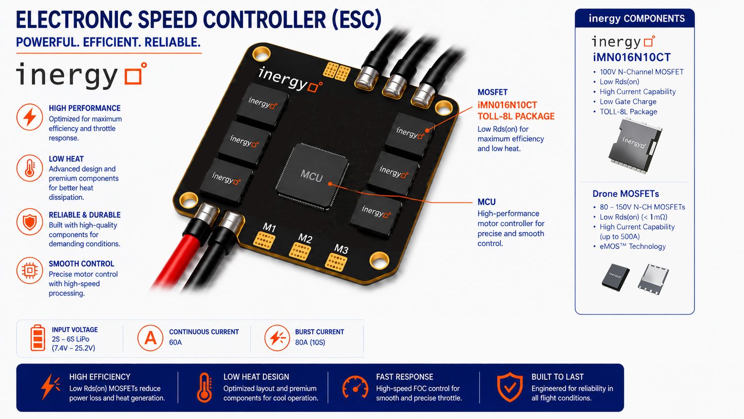
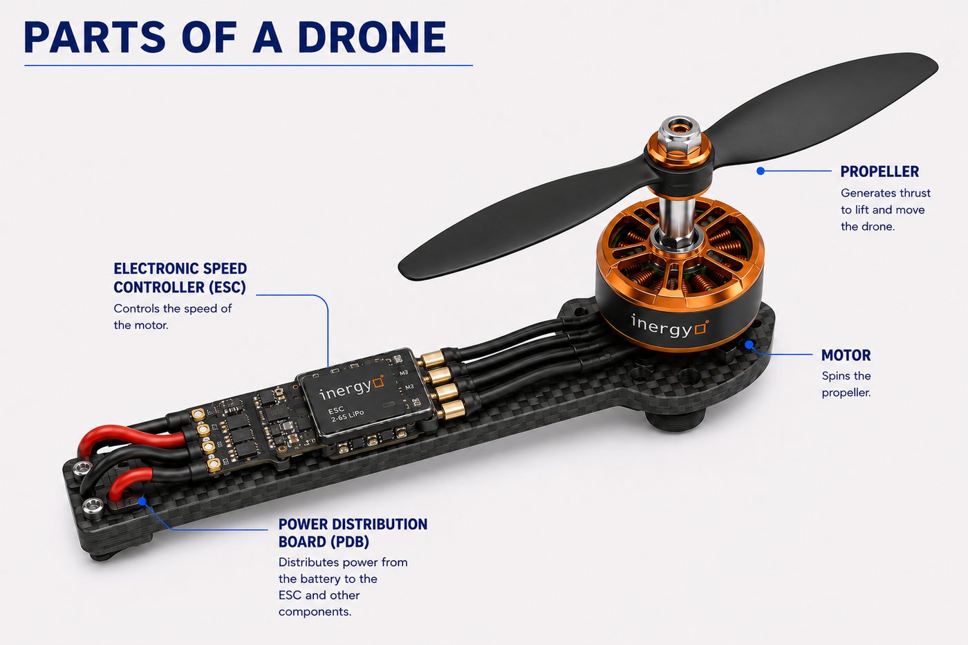
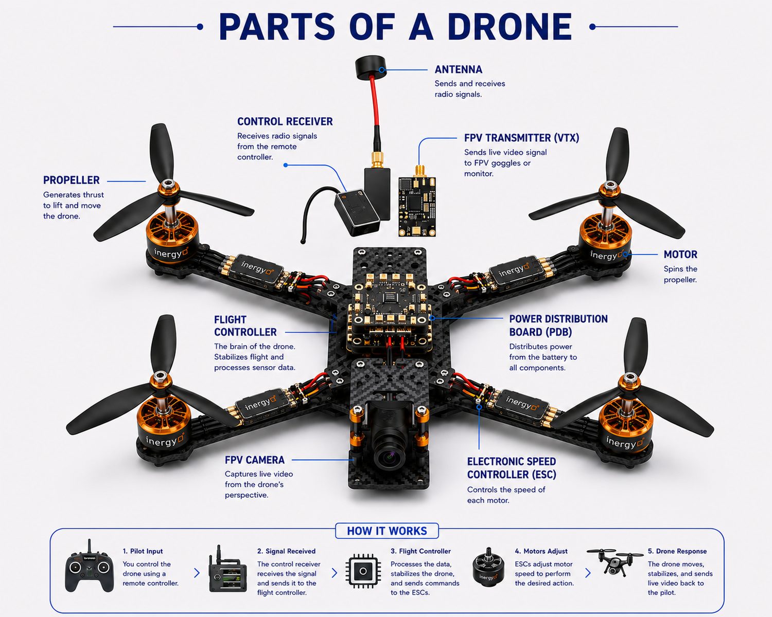
The ESC takes a DC rail from the power distribution board and commutates it into the three motor phases. Six MOSFETs do that switching, at up to hundreds of amps, inside a package the size of a postage stamp.
The switching job, briefly
Each phase needs a high-side and a low-side device. At hover the duty cycle is steady and conduction loss dominates, so Rds(on) sets the ESC's temperature. In aggressive throttle and high-PWM FOC the gate is charged and discharged tens of thousands of times a second, and Qg sets the loss instead.
That is why the portfolio carries matched pairs like iMN1R5N08G and ‑GH: same PDFN5x6C footprint, one trading 0.1 mΩ of conduction against 12 nC of gate charge. Pick by which loss your platform is actually limited by.
Battery configuration and VDS
Size from the charged pack voltage, then leave derating margin for switching-node ringing, long battery leads, and regenerative braking on descent.
| Battery size | Nominal voltage | Max voltage (charged) | Industry VDS | inergy ESC line |
|---|
The industry VDS column is the conventional sizing table. The inergy column is our own mapping for ESC motor-drive stages, which carries deliberately more margin than the minimum. For 1S–3S micro classes, talk to us about the wider selection guide.
Design-in path
Four steps, in the order they usually happen. Most customers reach volume pricing within one design cycle.
Request samples
Evaluation samples of the 60V / 80V / 100V devices, shipped against your ESC schematic.
BOM cost review
A joint session to quantify savings in your specific design versus current sourcing. Real numbers on the table.
Design-in support
FAE support for schematic review, PCB layout, thermal analysis, and device selection for your exact platform.
Volume agreement
Volume pricing and supply security aligned to your production ramp. Taiwan-based manufacturing.
Tell us about your ESC
Send us the cell count, continuous and burst current, and the board area you have for the power stage. We will come back with a device shortlist and sample availability.